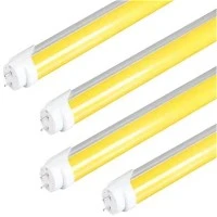

Case file: a PCB dry-film workshop, early shift. Three batches in a row show faint ghost patterns on the copper. The exposure machine has been calibrated twice. The resist lot is new but passes every incoming check. The only thing anyone changed that month was a handful of ceiling tubes, replaced after a few had burned out. They were yellow, they were cheap, and they looked exactly like the old ones.
This scenario is a composite, but any engineer who has worked in a yellow room will recognise the pattern. When photoresist or dry film misbehaves for no obvious reason, the light on the ceiling is one of the first suspects. The rest of this article follows the evidence: what the resist actually reacts to, what a proper yellow tube must block, and what you should ask a supplier to prove before you replace a single lamp.

Exhibit A: what the photoresist actually "sees"
Photoresist is a light-sensitive coating, and it does not care how bright a lamp looks to a human. It cares about wavelength. The study on LEDs as ambient light for photolithography rooms found that all the photoresists it examined were sensitive only to wavelengths below about 460 nm, and that rooms are called "yellow rooms" precisely because their light sources emit nothing below roughly 500 nm. A patent on LED-based cleanroom lighting adds that many resists absorb strongly at the mercury emission lines of 435, 405 and 365 nm, and that some newer resists also absorb below roughly 380 nm.
| Wavelength | What it is | Position vs. 500 nm cut-off |
|---|---|---|
| 365 nm | Mercury i-line, exposes novolac and many other resists | 135 nm below (blocked) |
| 405 nm | Mercury h-line, strong resist absorption | 95 nm below (blocked) |
| 436 nm | Mercury g-line, the main sensitivity peak of many resists | 64 nm below (blocked) |
| ≈460 nm | Upper edge of photoresist sensitivity in the study above | 40 nm below (blocked) |
| 500 nm | Cut-off of this tube | Cut-off |
| 555 nm | Peak sensitivity of the human eye | 55 nm above (passed) |
| ≈590 nm | Main wavelength of the Benwei yellow tube (per product FAQ) | 90 nm above (passed) |
The table shows the logic of the design. The nearest dangerous line, the g-line, sits 64 nm below the cut-off, and the usable yellow light sits comfortably above it. That gap is the safety margin. It is why serious suppliers talk about blocking below 500 nm and not about "yellow colour".
Exhibit B: the spectrum, and why the eye barely notices the cut
A natural worry is that filtering out everything below 500 nm will leave the room dim. The chart below answers it with the standard photopic sensitivity curve of the human eye. The shaded zone is what an anti-UV tube removes; the curve shows how much of the eye's sensitivity lives there.
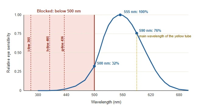
The eye's sensitivity at 436 nm is about 2% of its peak, and at 500 nm it is still only about 32%. In other words, the light a yellow room removes is light that people barely use to see. That is why filter makers such as MicroChemicals describe the ideal yellow filter as one that blocks everything under 500 nm below the detection limit while transmitting the region above 540 nm, near the eye's maximum, so that cleanroom lighting stays reasonably efficient.
Exhibit C: "yellow" and "anti-UV" are not the same thing
Here is the heart of the case. Yellow is a colour you see; anti-UV is a spectrum you measure. A tube can look yellow to the eye and still leak a little violet and blue, because a thin yellow tint changes the colour of the light without removing the short wavelengths. For resist, a leak of even a small share of 405 or 436 nm over many hours of storage is enough to matter. MicroChemicals states that resist-coated substrates kept under yellow light for hours require wavelengths below 500 nm to be blocked beyond the detection limit.
| Light source | Cut-off wavelength | What to know |
|---|---|---|
| Ordinary white tube (400–700 nm) | None | Includes g-, h- and i-line energy; unsuitable for exposed resist areas |
| White fluorescent with plastic film (older practice) | ≈ 450 nm | Film blocks light up to 450 nm, as described in a patent on lithography lighting |
| Fluorescent tube with yellow filter sleeve | ≈ 500 nm | Typical design; the sleeve absorbs what resists are sensitive to |
| UV-protection yellow sleeve, Y520 | < 520 nm | Made for T5 and T8 lamps; a stricter cut-off for sensitive work |
| Benwei T8 yellow anti-UV LED tube | < 500 nm | Main wavelength ≈ 590 nm, CCT 1500–2000K, spectral report on request |
Notice that the sensible range runs from about 450 nm to 520 nm depending on the process. The number you need comes from your resist datasheet, which is why a supplier should be able to tell you the cut-off in nanometres and back it with a measurement, not only a colour name.
Exhibit D: will it still be bright enough to work under?
Blocking light costs brightness, and the room still has to be safe and comfortable for operators. The Benwei guide to why cleanrooms need yellow light tubes quotes 500–750 lx for photolithography areas. Using that range, here is a rough count for a 40 m² bay, assuming 110 lm/W (the middle of the tube's 100–120 lm/W) and a combined utilization and maintenance factor of 0.4:
| Tube (representative power) | Approx. output | Tubes for 500 lx (50,000 lm needed) |
Tubes for 750 lx (75,000 lm needed) |
|---|---|---|---|
| 10W, 600 mm | ≈ 1,100 lm | 46 (460 W) | 69 (690 W) |
| 14W, 900 mm | ≈ 1,540 lm | 33 (462 W) | 49 (686 W) |
| 20W, 1200 mm | ≈ 2,200 lm | 23 (460 W) | 35 (700 W) |
| 25W, 1200–1500 mm | ≈ 2,750 lm | 19 (475 W) | 28 (700 W) |
Calculated with required lumens = lux × area ÷ 0.4. Wattages are representative values inside the ranges on the product page (8–35W). A final layout needs a photometric check against your ceiling grid and fixture type.
As in any lighting calculation, the connected load barely changes with tube size; what changes is how many fixtures you wire and how evenly the bay is lit. Higher power does not weaken the filter, because the product FAQ explains that blocking depends on the optical cover material, not on wattage. One more practical point from the patent literature: yellow light is poor for maintenance work, so many fabs keep a separate white circuit for cleaning and repairs, interlocked so it cannot be switched on during processing. A high-CRI tube such as our 97Ra/95Ra T8 suits that second circuit.

Evidence to request before you swap a single lamp
If the case file at the top were your workshop, these four documents would close it quickly. The Benwei T8 yellow anti-UV LED tube offers all of them, according to its listing:
| Ask for | Why it matters | Available? |
|---|---|---|
| Spectral test report | Shows the real cut-off and any leakage below 500 nm | On request; each batch is sampled |
| Efficacy and CCT data | Confirms brightness after filtering (100–120 lm/W) and the colour (1500–2000K) | Yes, in the specification |
| EU conformity documents | Needed for customs clearance | LVD, EMC, RoHS and DoC; ErP on request |
| Retrofit details | Avoids rewiring surprises on G13 fixtures | Single-end power and integral aluminium versions |
Case closed: send us the bay, and we will send a sample
Every yellow room has its own resist, its own cut-off requirement and its own ceiling. The fastest route is to tell us three things: the resist or dry-film datasheet wavelength you need to protect, the room size and target lux, and whether you are retrofitting G13 fixtures or building new. We will recommend the tube length, power and cover (clear or frosted) and quote a sample. The wider special T8 LED tube range includes a 480–520 nm filter version for processes that need a different cut-off.
Reach the Benwei team through the inquiry page, by email at bwzm88@benweilighting.com. Free samples are available.