
Non-Isolated LED Drivers: The Technical Trade-offs and Safety Imperatives Behind Cost-Effectiveness
In the commercial and industrial LED lighting sector, the pursuit of higher system efficacy (Luminaire Efficacy) and lower first cost is a constant imperative. The once-dominant isolated driver solution, traditionally favored for safety, now faces a significant challenge from the increasingly prevalent non-isolated LED driver. Advances in semiconductor technology and insulating materials have led to greater acceptance and application of these driver architectures that directly couple mains voltage to the LED load. However, what does this "high-voltage direct coupling" truly entail? What essential knowledge must designers and specifiers master to make informed decisions balancing performance, cost, and safety?
I. Core Concept: What Does "Non-Isolated" Mean?
To understand non-isolated drivers, one must first clarify the definition of "isolation." In switch-mode power supplies, "isolation" refers to creating a barrier with no direct electrical connection between the input (primary side, typically connected to high-voltage AC) and the output (secondary side, connected to the LED load) via a high-frequency transformer. This barrier not only enables voltage transformation but also provides crucial safety isolation and noise suppression.
In contrast, a non-isolated LED driver employs a more direct high-voltage direct-coupling architecture. It typically uses DC-DC topologies like Buck (step-down), Boost (step-up), or Buck-Boost converters to regulate voltage directly from the rectified and filtered high-voltage DC bus to power the LED load. The input and output are connected only through impedance or feedback networks, lacking the electrical isolation of a transformer [1]. This fundamental difference triggers a series of consequential trade-offs.
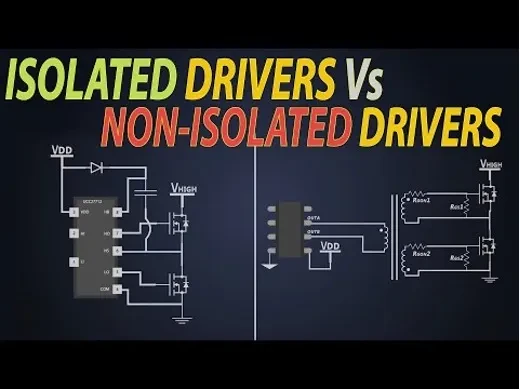
II. Technical Deep Dive: Operating Principles and Core Challenges of Non-Isolated Architecture
The core of a non-isolated driver lies in its simplified power stage design. Taking the most common non-isolated Buck converter as an example, its workflow can be summarized as follows:
AC Rectification: Input AC (e.g., 220V AC) is converted into a high-voltage DC bus (approx. 310V DC) via a bridge rectifier and filtering capacitor.
Power Switching Modulation: A control IC drives a power MOSFET switch, performing high-frequency PWM chopping on the high-voltage DC.
LC Filtering & Output: The chopped pulse voltage is smoothed into a stable DC current by an inductor (L) and capacitor (C) filter network, directly driving the LED string.
Current Sensing & Feedback: Output current is monitored via a sense resistor (Rsense) in series with the LED loop, forming a closed-loop control for constant current drive.
While this architecture eliminates the transformer, it elevates high-voltage bus management and thermal design as critical challenges. Since the LED load's negative (or positive, depending on topology) terminal may be directly connected to the rectified high-voltage bus, the entire LED metal-core PCB (MCPCB) and potentially the luminaire housing can carry a high voltage potential relative to earth. This imposes stringent demands on the luminaire's insulation system design, requiring absolute certainty that live parts cannot be contacted by a user under any circumstance.
III. Isolated vs. Non-Isolated: A Comprehensive Decision-Making Comparison Table
Choosing between these driver solutions is not a simple binary decision but a systematic trade-off based on the specific application context. The table below summarizes the core differences between the two technological paths:
| Comparison Dimension | Isolated Driver | Non-Isolated Driver |
|---|---|---|
| Electrical Safety Principle | Relies on a transformer to provide reinforced insulation between input/output, meeting SELV (Safety Extra-Low Voltage) standards. The output side is touch-safe. | No transformer isolation. Relies on the luminaire's overall basic insulation and protective earth connection (Class I construction) to prevent electric shock. The output side carries hazardous voltage. |
| Typical Efficiency | Affected by transformer core and winding losses. Efficiency typically ranges from 87% to 92%. | Fewer components in the power path lead to lower losses. Efficiency commonly reaches 90% to 95% or higher, contributing to superior luminaire efficacy. |
| Size & Power Density | The transformer occupies significant space, resulting in a relatively larger volume and lower power density. | No transformer allows for a more compact high-density circuit layout, ideal for size-sensitive applications (e.g., downlights, light strips). |
| Cost Structure | Higher cost for magnetic components (transformer), optocouplers, etc. Circuitry is relatively complex. | Component count is reduced by approximately 20%-30%, leading to significantly lower BOM cost and a distinct price competitive advantage. |
| Reliability & Lifetime | The transformer provides a natural barrier against surges and noise, offering stronger protection for the LED load. Lifetime is often limited by electrolytic capacitors. | High-voltage stress is applied directly to power switches and LEDs, demanding high-quality components and strict PCB creepage and clearance distances. Excellent ESD and surge protection circuits are essential. |
| Maintenance & Installation | Installation is relatively safe; maintenance personnel face no direct risk when handling the low-voltage secondary side. | Strict adherence to Class I grounding codes is mandatory. Installation, debugging, and maintenance require power disconnection and verification of discharge, demanding higher operator expertise. |
| Typical Application Scenarios | Outdoor lighting, damp environments (IP65+), touchable luminaires (e.g., desk lamps, panel lights), markets with stringent safety certification requirements. | Well-insulated indoor luminaires (e.g., recessed downlights, troffers), luminaires with protective housings, cost-sensitive commercial projects, and space-constrained ultra-slim optical designs. |

IV. Safety First: Non-Negotiable Red Lines for Non-Isolated Driver Application
Despite their attractive efficiency and cost, the application of non-isolated drivers must be built upon an uncompromising foundation of safety. The following points are cornerstones of engineering practice:
Mandatory Class I Grounding (Protective Earth): This is the lifeline for non-isolated solutions. The luminaire's metal housing must be reliably connected to the mains protective earth (PE) via a low-impedance path, ensuring any fault current triggers the circuit breaker.
Robust Insulation System Design: High-strength insulating thermal pads (e.g., rated for 3kV or higher) with high thermal conductivity must be used between the LED MCPCB and the heatsink. PCB layouts must meet stricter requirements for creepage distance and electrical clearance between primary-side circuits and touchable parts to mitigate risks from humidity or dust [2].
Comprehensive Protection Circuitry: Beyond over-temperature and over-current protection, effective differential and common mode surge suppression (e.g., using MOVs, GDTs) is essential to protect vulnerable LEDs and driver ICs from transient voltage spikes on the grid.
V. Market Trends and Rational Selection
Currently, with improvements in insulating material performance and increasingly robust protection features in driver ICs, the application of non-isolated solutions in controlled indoor environments is steadily expanding. Many leading luminaire manufacturers adopt a hybrid strategy: insisting on isolated drivers for premium, high-reliability product lines; while offering solutions based on high-performance non-isolated driver ICs for cost-critical projects with controlled installation environments.
For project decision-makers, the choice should be based on a system-level risk assessment:
Choose an Isolated Driver: When safety is the absolute top priority, the application environment is uncontrolled, or end-users might directly touch the luminaire.
Consider a Non-Isolated Driver: For indoor dry-environment projects with tight budgets, stringent efficacy requirements, professional installation/maintenance, and where the luminaire's mechanical design can guarantee proper grounding and insulation.
FAQ
Q1: Are non-isolated drivers always cheaper than isolated drivers?
A: From a Bill of Materials (BOM) cost perspective, typically yes. However, the total system cost must be considered. Using a non-isolated driver may necessitate more expensive insulating materials, stricter grounding structures, and more complex testing and certification on the luminaire side. These costs can offset the driver's price difference. The final cost depends on the specific design and procurement scale.
Q2: Can non-isolated driver solutions achieve international safety certifications like CE or UL?
A: Yes, but the certification path and clauses differ. For instance, under UL standards, isolated drivers often follow a combination of UL8750 (LED Equipment) + UL1310 (Class 2 Power Units). Non-isolated drivers are typically evaluated under UL8750 + UL1598 (Luminaire Standard), with a heavy focus on testing ground continuity, insulation strength, and fault conditions. The certification process is often more challenging and complex.
Q3: During repair or replacement, can I directly swap a luminaire's original isolated driver for a non-isolated one?
A: Absolutely forbidden! This is an extremely hazardous practice. The two driver types have fundamentally different output characteristics, safety architectures, and luminaire design requirements. Substituting them can not only damage the luminaire but also create a lethal shock risk due to the loss of necessary insulation or grounding protection. Driver replacement must strictly follow the original design specifications or be conducted under the guidance of a qualified professional.
Q4: How significant are the practical benefits of the "higher efficiency" of non-isolated drivers in real-world projects?
A: The efficiency advantage is meaningful in large-scale projects. Consider a commercial project with 10,000 luminaires at 60W each, running 4,000 hours annually with an electricity cost of $0.12/kWh. A 3% improvement in driver efficiency would yield annual savings of approximately: 10,000 * 60W * 3% * 4,000h / 1000 * $0.12 ≈ $8,640. Over the long term, these savings become substantial.
References & Notes
[1] Mohan, Undeland, Robbins. Power Electronics: Converters, Applications, and Design. 3rd Edition. Wiley, 2002. (Authoritative text on non-isolated DC-DC converter topologies.)
[2] International Electrotechnical Commission. IEC 61347-1:2015 *"LED controlgear - Part 1: General and safety requirements"*. (Core international standard for LED driver safety, detailing insulation, creepage, and clearance requirements.)
[3] Application Notes and Design Guides from leading LED driver IC manufacturers (e.g., TI, MPS, Infineon) for non-isolated Buck/Buck-Boost drivers serve as direct technical references for practical engineering design.