
Introduction: The Driver Is the Hidden Determinant of LED Lifespan
The Field Data That Changes the Conversation
Lighting buyers are trained to evaluate LED bulbs on chip brand and lumen output. The implicit assumption is that the chip is the durable component and that the rest of the bulb is supporting infrastructure. Field data from commercial and industrial projects contradicts that assumption with uncomfortable consistency.
A failure analysis of 3,200 defective LED lamps found that 72% of all lamp failures were directly caused by defective drivers, and a further 16% by aging capacitors inside drivers-a combined 88% of faults attributable to the driver subsystem. LED chips accounted for only 4% of failures, meaning the chips were almost always intact when the lamps stopped working. The same analysis noted the barrel-effect logic: LED chips carry a theoretical lifespan of 100,000+ hours, while ordinary low-cost drivers last 15,000 to 25,000 hours, making the driver the lifespan bottleneck of the entire lamp.
This data reframes the durability question. A bulb's lifespan is not a chip property that the driver passively supports. It is a driver property that the chip happens to illuminate. The IC constant-current driver in the product evaluated here is the component that determines whether the bulb reaches its projected service interval or becomes a maintenance line item within the first few years.
The Two Functions of the Driver: Regulation and Protection
The driver performs two distinct functions, and both are consequential for lifespan. The first is current regulation: it converts the mains AC supply into the stable direct current that the LED array requires, holding that current constant despite input voltage fluctuation and forward-voltage variation across chips. The second is protection: it shields the LED array and itself from the electrical and thermal stresses of real installations-surges, noise on the mains supply, and the heat generated by continuous operation.
A driver that regulates well but protects poorly will fail at its own weakest component. A driver that protects well but regulates poorly will allow the LED to flicker, shift color, or degrade prematurely. The product's IC constant-current design addresses both functions, and the anti-interference specification is the evidence that the protection function was treated as an engineering requirement rather than an afterthought.
The Structure of the Argument
The article proceeds from physics to system to specification. Section 2 establishes the constant-current necessity: the LED's negative temperature coefficient and the thermal-runaway risk under constant-voltage drive. Section 3 examines the electrolytic capacitor as the driver's limiting component and shows how the 10°C rule converts the bulb's thermal architecture into a quantified life extension. Section 4 examines the anti-interference and protection functions that keep the driver stable under electrical stress. Section 5 synthesizes the evidence into a system-level lifespan model, and Section 6 translates it into a purchasing specification.
Constant Current as a Physical Necessity, Not a Design Preference
The LED's Negative Temperature Coefficient
An LED is a diode, and its forward voltage has a negative temperature dependence: as the junction temperature rises, the forward voltage drops. The temperature coefficient is typically in the range of −1.5 to −2.5 mV/°C, with some sources citing −2 mV/°C as a working figure. This means that at a fixed forward voltage, a warmer LED draws more current than a cooler one.
Under constant-voltage drive, this relationship creates a positive feedback loop. The LED warms, its forward voltage drops, the fixed voltage drives more current through it, the increased current generates more heat, the junction temperature rises further, and the forward voltage drops again. The loop is self-reinforcing. Patent literature describes the mechanism precisely: an elevation in temperature lowers the forward voltage and increases the forward current, and "the increased forward current promotes further elevation of the temperature… This is a state of positive feedback in terms of power, which can eventually lead to thermal runaway". Chinese patent literature on constant-current drive reaches the same conclusion, describing the temperature rise, resistance decrease, current increase, and further temperature increase as a positive feedback that can cause the LED to fail.
How Constant-Current Drive Breaks the Loop
Constant-current drive converts the feedback from positive to negative. Instead of fixing the voltage and allowing the current to rise, the driver fixes the current and allows the voltage to settle wherever the LED's forward characteristics require. When the LED warms and its forward voltage drops, the driver reduces its output voltage to maintain the set current. The power dissipated in the LED remains constant rather than rising, and the thermal runaway loop is broken at its source.
The patent description of this mechanism is explicit: "even if the temperature elevation lowers the forward voltage of the LED, the drive circuit comes to a state of negative feedback in terms of power to keep the current flowing in the LED constant. Therefore, it advantageously operates to suppress an overcurrent in the LED, preventing the temperature in the LED from elevating due to self-exothermicity, and preventing thermal runaway from occurring".
For the high-power E27 bulb, this is not a theoretical nicety. A high-wattage LED array in a compact envelope generates substantial heat, and the junction temperature rise under continuous duty is precisely the condition that would trigger the positive-feedback loop under constant-voltage drive. The IC constant-current driver is the component that makes high-wattage operation physically safe. Without it, the bulb would be a thermal-runaway risk rather than a long-life product.
Current Accuracy and the Stability of the Operating Point
Constant-current regulation is not a binary property. The accuracy with which the driver holds the set current determines how far the LED's operating point can drift under thermal and electrical variation. Published specifications for LED driver ICs in this class cite output current accuracy in the range of ±3% to ±5%, with feedback voltage references as low as 0.25 V ± 3%. A tighter current tolerance means a more stable operating point, which in turn means more consistent light output, more predictable thermal behavior, and less stress on the LED chip over time.
The anti-interference function is related but distinct. Current accuracy describes how well the driver holds its target under stable conditions; anti-interference describes how well it rejects disturbances that would otherwise perturb the target. A driver with good accuracy but poor interference rejection will hold its current precisely until a disturbance arrives, then deviate. A driver with both properties holds its current precisely through the disturbances that real electrical environments present. The product's "anti-interference" specification is therefore a statement about the second property, and it is the property that matters most in installations where the driver shares a supply with motors, compressors, or switching equipment.
The Electrolytic Capacitor: The Driver's Weakest Link and the 10°C Rule
Why the Capacitor, Not the Chip, Sets the Service Ceiling
The constant-current driver regulates current, but it does so through a circuit that includes an aluminum electrolytic capacitor for energy storage and filtering. The capacitor holds up the voltage between the peaks of the AC supply and smooths the rectified DC that the driver delivers to the LED array. Its construction-aluminum foil with a wet dielectric material-makes it the component most sensitive to temperature within the driver assembly.
The failure mechanism is gradual electrolyte loss. The electrolyte dries out over time, the capacitance decreases, and the equivalent series resistance (ESR) rises. As ESR rises, power dissipation increases for a given ripple current, which generates more heat, which accelerates the drying-out process. The capacitor does not fail suddenly; it decays slowly until the driver can no longer hold its output within specification, and the lamp exhibits flicker, reduced brightness, or outright failure.
This is why the driver's lifespan is often defined by its capacitor. A good-quality electrolytic capacitor may be rated for 10,000 hours at 105°C, and that rating becomes the ceiling on the driver's useful life unless the capacitor is operated below its rated temperature. The LED chip's 50,000-hour projection is irrelevant if the capacitor reaches its end of life at 20,000 hours.
The 10°C Rule and the Arithmetic of Life Extension
The relationship between capacitor temperature and capacitor life is governed by the Arrhenius equation, and it is consistently stated across the reliability literature: every 10°C reduction in operating temperature approximately doubles the capacitor's expected life, and every 10°C increase halves it.
The arithmetic is straightforward and consequential. A capacitor rated at 10,000 hours at 105°C, operated at 85°C-a 20°C reduction-has a projected life of approximately 40,000 hours, a factor of four. Operated at 75°C, the projection rises to approximately 80,000 hours. The same capacitor, in the same driver circuit, can deliver a fourfold or eightfold difference in service life depending purely on the thermal environment in which it operates.
This arithmetic converts the bulb's thermal architecture from a generic "cooling feature" into a specific lifespan multiplier. The aluminum fin heat sink and the built-in active fan are not merely LED coolers. They are capacitor-life extenders, because they lower the air temperature inside the driver compartment, and the capacitor's life is exponentially sensitive to that temperature.
The Fan and Fins as Capacitor-Life Multipliers in the E27 Envelope
The high-power E27 form factor makes the capacitor's thermal environment especially consequential. The driver sits in the base of the bulb, adjacent to the LED board and the fin structure. In a passive design, the heat generated by the LED and the driver accumulates in the confined volume of the bulb, raising the capacitor's operating temperature above the ambient and shortening its life accordingly.
The product's architecture addresses this directly. The aluminum fins conduct heat away from the LED board and the driver, spreading it across a surface area large enough for convective transfer to the surrounding air. The built-in fan forces air across the fin surfaces, increasing the convective coefficient and moving heat out of the bulb at a rate that passive finning alone cannot achieve in the restricted-airflow environments that real fixtures present.
The effect on the capacitor is quantified by the 10°C rule. If the fan-and-fin architecture reduces the driver compartment temperature by 10–15°C relative to a passive design, the capacitor's projected life extends by a factor of two to nearly three. If it reduces the temperature by 20°C, the factor approaches four. This is the mechanism by which the thermal architecture directly extends the bulb's lifespan: not by making the LED brighter, but by keeping the driver's weakest component within a temperature range where its rated life is actually achievable.
Patent literature on LED power-drive cooling confirms the logic. A utility model for a power-driven cooling device for LED lamps describes a fan positioned opposite the electrolytic capacitor on the driver board, with the explicit purpose of blowing heat away from the capacitor, reducing its temperature, and "prolonging the service life of the electrolytic capacitor". The principle is not speculative. It is an established design strategy for exactly the failure mode that dominates field data.
Anti-Interference and Protection: Stability Under Real Electrical Conditions
What "Anti-Interference" Means in a Driver Specification
The term "anti-interference" describes the driver's ability to maintain stable current delivery in the presence of electrical disturbances on the mains supply. Commercial and industrial electrical environments are not clean. Motors, compressors, forklift chargers, HVAC equipment, and variable-frequency drives inject noise and transients onto the supply that a driver shares. A driver that lacks interference rejection will pass those disturbances through to the LED current, producing flicker, color shift, or reduced output.
The product's anti-interference design is implemented at the IC level. Driver ICs in this class incorporate functions such as PWM dimming with stable duty-cycle translation, electromagnetic interference (EMI) mitigation, and built-in protection circuits including overvoltage protection, undervoltage lockout, and thermal shutdown. These functions are not marketing additions. They are the circuit-level mechanisms that keep the driver's output within specification when the input is not within specification.
Current Ripple, Flicker, and the Cumulative Stress on the LED
Interference and ripple are related concerns. A driver with high current ripple delivers a pulsating current to the LED array, and that pulsation produces flicker and imposes a cyclic thermal stress on the chip. Premium drivers are specified for "ultra-low current ripple, 100% flicker-free" operation, while budget non-isolated drivers exhibit "high current ripple" and "invisible high-frequency stroboscopic light" that "accelerates chip aging day by day".
The mechanism is thermal cycling. Each ripple cycle produces a small temperature excursion at the junction, and the cumulative effect of millions of such excursions is material fatigue at the solder joints and wire bonds. A driver that suppresses ripple reduces that cumulative stress, which preserves the LED's lumen maintenance and color stability over the service life. The anti-interference design and the ripple suppression are therefore two aspects of the same stability objective: keep the current as close to a clean DC as the circuit can achieve, so that the LED experiences a steady operating point rather than a continuously fluctuating one.
Protection Functions as Lifespan Insurance
The integrated protection functions in the driver IC serve as lifespan insurance against events that would otherwise be terminal. Overvoltage protection prevents a mains transient from driving the output beyond the LED array's safe operating range. Undervoltage lockout prevents the driver from operating in a marginal condition where current regulation would be unreliable. Thermal shutdown reduces or cuts output when the driver's internal temperature exceeds a safe threshold, protecting the capacitor and the IC itself from damage.
These functions do not improve the bulb's performance under normal conditions. They preserve it under abnormal ones. In a commercial installation, abnormal conditions are not rare-they are the reason field failure data exists. A driver with integrated protection is a driver that converts a potentially terminal event into a temporary interruption, and that is a direct contribution to the system's realized service life.
Surge Protection and the Difference Between Premium and Budget Drivers
The protection gap between driver grades is visible in published comparisons. A premium isolated driver is specified for 4kV anti-surge protection, 105°C high-temperature capacitors, and an average actual lifespan of 50,000 hours matching the LED chip. A budget non-isolated driver is specified with almost no surge protection module, 85°C ordinary electrolytic capacitors, and an average actual lifespan of 18,000 hours, far shorter than the LED chip it serves.
The difference is not a matter of degree. It is the difference between a bulb whose driver lifespan matches its chip lifespan and a bulb whose driver fails long before the chip reaches its service limit. The product's IC constant-current design, with its anti-interference and protection functions, belongs to the first category. The specification is the evidence, and the field data is the consequence.
System-Level Lifespan Modeling: How the Pieces Interlock
The Cascading Protection Logic
The driver and the thermal architecture are not independent improvements. They are coupled in a cascading protection logic that determines the bulb's actual service life.
The fan and fins lower the temperature of the entire driver compartment. That lowers the capacitor's operating temperature, which extends the capacitor's life according to the 10°C rule. It also lowers the temperature of the driver IC, which reduces thermal stress on the current-regulation circuitry and keeps the anti-interference functions operating within their specified windows. The IC constant-current regulation, in turn, prevents the LED from experiencing the current runaway that would occur under constant-voltage drive, which keeps the LED's thermal load within the range that the fins and fan were designed to handle. And the protection functions intercept the abnormal events that would otherwise produce a single-point failure.
Each subsystem protects the others. The thermal architecture protects the driver's capacitor. The driver's regulation protects the LED from thermal runaway. The driver's protection functions protect both the driver and the LED from electrical transients. The system's lifespan is not the lifespan of any single component. It is the lifespan of the weakest link in this protected chain, and the architecture is designed to raise that weakest link to the level of the strongest.
Quantifying the Combined Effect
A simplified model illustrates the scale of the combined effect. Consider a driver with a 105°C/10,000-hour capacitor operating in a bulb without active cooling, where the driver compartment reaches 85°C. The capacitor's projected life is 40,000 hours. Now consider the same driver in the product's architecture, where the fan and fins reduce the compartment temperature to 70°C. The capacitor's projected life rises to approximately 80,000 hours-a doubling of the driver's service ceiling from the thermal improvement alone.
Add the effect of stable current regulation and protection functions. The LED operates at a steady operating point rather than a fluctuating one, which reduces cumulative thermal cycling stress and preserves lumen maintenance. The protection functions prevent transient events from producing premature failure. The realized service life moves closer to the capacitor's projected ceiling rather than being cut short by an avoidable electrical event.
The combined effect is not additive in a simple arithmetic sense. It is multiplicative in the sense that each improvement removes a constraint that would otherwise limit the benefit of the others. The fan extends capacitor life; the constant-current regulation extends LED life; the protection functions preserve both. The system's lifespan is the outcome of all three working together, and that is why the driver-not the chip-is the correct focal point for a durability specification.
What the Driver Cannot Fix
A candid assessment requires acknowledging the boundary conditions. The driver cannot compensate for an inadequate fixture environment. If the bulb is installed in a sealed enclosure with no airflow, the fan's cooling capacity is reduced and the driver compartment temperature will rise regardless of the thermal architecture. If the mains supply is subject to severe and repeated surges beyond the protection circuit's rating, the driver will eventually fail. If the capacitor is a low-grade 85°C component rather than a 105°C component, its baseline life is shorter and the 10°C rule starts from a lower ceiling.
The driver is the determinant of lifespan within the conditions the installation provides. It is not a substitute for those conditions. The purchasing decision should therefore pair the driver specification with a fixture assessment, so that the driver's protection and thermal management are matched to the environment in which they will operate.
Specification and Purchasing Framework
Verify Constant-Current Topology and Current Accuracy
Confirm that the driver is a constant-current design rather than a constant-voltage or simple resistor-capacitor arrangement. Request the output current accuracy specification, with ±5% as a working minimum and tighter tolerances preferred. A constant-current driver is the physical precondition for thermal-runaway prevention and stable light output. Without it, the other specifications are built on an unstable foundation.
Ask About the Capacitor, Not Just the Driver
The driver's lifespan is often the capacitor's lifespan. Request the capacitor's temperature rating (105°C preferred over 85°C) and its rated life at that temperature. A 105°C/10,000-hour capacitor operated at 70–75°C projects to 80,000 hours or more under the 10°C rule. An 85°C capacitor in the same position starts from a shorter baseline and reaches its limit sooner. The capacitor specification is the most direct available proxy for the driver's service ceiling.
Confirm the Thermal Path That Protects the Capacitor
The driver's capacitor life depends on the temperature of the driver compartment. Confirm that the bulb's thermal architecture-aluminum fins and active cooling-is designed to move heat away from the driver, not only from the LED board. The fan's airflow path should include the driver compartment, and the fin structure should conduct heat from the driver's heat-generating components toward the external surfaces. A thermal design that cools the LED but leaves the driver in a stagnant hot zone has missed the component that most often fails first.
Evaluate Anti-Interference and Protection Functions
Request the driver's anti-interference and protection specifications: EMI mitigation, current ripple, overvoltage protection, undervoltage lockout, and thermal shutdown. These functions are not visible in the light output, but they determine whether the driver survives the electrical environment it is installed in. A driver with integrated protection is a driver that converts abnormal events into temporary interruptions rather than permanent failures.
Match the Driver Specification to the Installation Environment
A premium driver in a poorly ventilated fixture will underperform its specification. A budget driver in a benign environment may survive longer than its rating suggests. The correct specification pairs a thermally protected, constant-current driver with a fixture that allows its thermal design to function. The driver is the lifespan determinant within the conditions the installation provides, and the purchasing decision should treat those conditions as part of the specification rather than as an afterthought.
Conclusion
The IC constant-current driver in this high-power E27 bulb is not a supporting component. It is the subsystem on which the bulb's lifespan claim rests. The physics of constant-current drive explain why: the LED's negative temperature coefficient creates a positive-feedback thermal runaway under constant-voltage drive, and constant-current regulation breaks that loop through negative feedback, holding the operating point stable as the junction temperature varies. The reliability data explain why the driver deserves this attention: 88% of field failures in a 3,200-lamp sample were attributable to the driver and its capacitor, while the LED chip accounted for only 4%. The chip is almost always intact when the lamp stops working.
Within the driver, the electrolytic capacitor is the limiting component, and the 10°C rule governs its life. The product's aluminum fins and active fan are not merely LED coolers. They are capacitor-life multipliers, because lowering the driver compartment temperature by 10–20°C extends the capacitor's projected life by a factor of two to four. The anti-interference and protection functions complete the picture: they keep the driver stable against electrical noise, suppress the current ripple that would otherwise accelerate LED aging, and intercept the transient events that would produce single-point failures. Together, these subsystems form a cascading protection logic in which each component extends the life of the others.
For the buyer, the practical lesson is that "driver" is not a generic term. A constant-current driver with a 105°C capacitor, a thermal path that protects it, and integrated anti-interference and protection functions is a driver that honors the bulb's rated life. A driver without those specifications is the component that will determine when the bulb fails, regardless of the chip inside it. The specification to write is not "long life." It is constant-current topology, capacitor temperature rating, thermal protection of the driver compartment, and anti-interference design-and those are the terms on which the lifespan claim is either supported or broken.
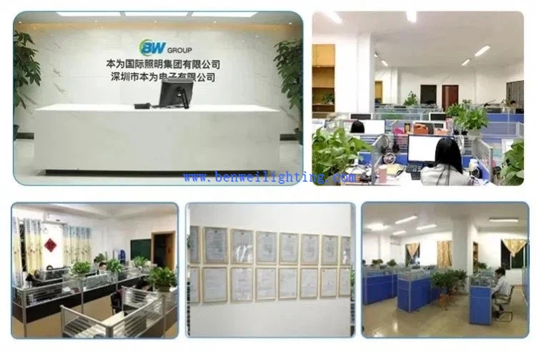
How To Cooperate With Us?
We are happy to have total control over the manufacturing process and the calibre of our products since we have our own facilities. Since we are producers rather than just brokers, we are dedicated to providing our customers with the best pricing. Since we are certain that the price and quality of our products are clear, we invite customers to see our samples first. Our commitment to quality and customer satisfaction drives us to continuously provide top-notch goods.
Our address
3rd Floor, 5th Building, Hebei Industrial Park, Hualian Community, Longhua District, Shenzhen, China