

How Can You Manage Voltage Drop in LED Lighting?
LED lighting is efficient, flexible, and suitable for everything from residential accent lighting to large commercial installations. However, long cable runs and poorly designed power distribution can create a common technical problem: Voltage Drop.
Voltage drop may cause LED strips to become dimmer toward the end of a run, produce inconsistent color, flicker, or place unnecessary stress on drivers and wiring. The good news is that it can usually be predicted during design and controlled through correct cable sizing, power injection, system voltage selection, and installation practices.
able of Contents
What Is Voltage Drop in LED Lighting?
Why Is Voltage Drop Critical for LED Performance?
How to Calculate Voltage Drop for Your LED Setup
Proven Solutions to Manage and Prevent Voltage Drop
Voltage Drop Best Practices in 2026
Frequently Asked Questions
Conclusion
What Is Voltage Drop in LED Lighting?
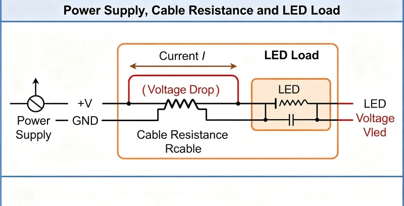
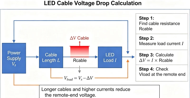
If you are asking what causes voltage drop in lighting, the short answer is resistance in the conductors that carry electrical current. Every cable has some resistance. When current passes through that resistance, part of the supply voltage is lost before it reaches the LED load.
The basic relationship is described by Ohm's Law:
V = I × R
Where:
V is voltage drop in volts
I is current in amperes
R is resistance in ohms
A longer cable generally has greater resistance. A smaller-gauge cable also has greater resistance than a larger-gauge cable of the same length. As current travels through the cable, electrical energy is converted into heat, and the voltage available at the LED becomes lower.
For example, suppose a 12 V LED strip is installed at the beginning of a long cable run. The power supply may deliver 12 V at the source, but the strip may receive only 11.2 V at the far end. Whether that reduction is acceptable depends on the product, current demand, cable length, and manufacturer specifications.
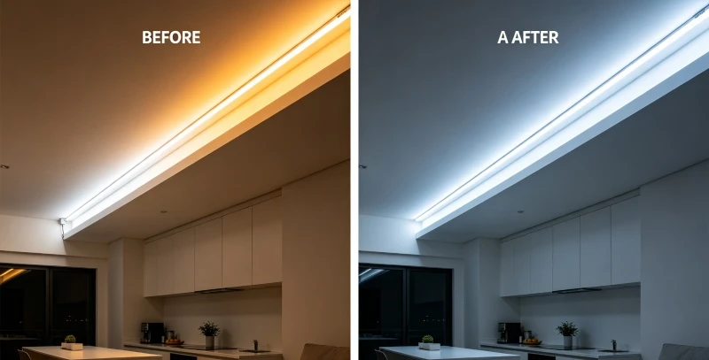
In a real installation, a strip may appear bright near the power connection but visibly dim several meters away. Installers sometimes replace the LED strip, increase the driver rating, or add more fixtures without checking the wiring. If the cable itself is undersized, these changes may not solve the underlying problem.
Voltage drop should therefore be considered during the design stage, not only after a lighting system performs poorly.
For a broader introduction to LED technology, see Benwei's related content. For additional background on the relationship between voltage, current, and resistance, consult these allaboutcircuits.com from an electrical engineering education resource.
Why Is Voltage Drop Critical for LED Performance?
Voltage drop vs power loss in LED systems is an important distinction. Voltage drop describes the reduction in voltage between the source and the load. Power loss describes energy dissipated in the cable, commonly calculated as:
P = I² × R
Both are related, but they are not identical. A system can experience a measurable voltage reduction while also losing power as heat in the wiring.
Common symptoms of excessive voltage drop
Voltage-drop problems often appear as:
LEDs that become dimmer farther from the power supply
Uneven brightness across a strip or linear fixture
Flickering during startup or when the system is dimmed
Color inconsistency between sections
Visible changes in color temperature
Driver overheating or repeated shutdown
Reduced system reliability and shorter component life
LEDs are particularly sensitive because their light output and electrical behavior depend on the operating current and forward voltage. An LED's forward voltage, often written as Vf, is the voltage required for the device to operate at a particular current and temperature.
In a constant-voltage LED strip, the strip is designed to receive a specified voltage such as 12 V or 24 V. If the voltage at the end of the strip falls significantly below the intended level, the current through the LED circuits may decrease. This can reduce brightness and cause color variation.
In constant-current systems, the driver is designed to regulate current within a defined operating range. Excessive cable resistance can still prevent the required voltage from reaching the fixture, causing the driver to lose regulation or shut down.
Symptoms of LED voltage drop
| Symptom | Technical cause |
Impact on the user |
|---|---|---|
| Dimming toward the end of a strip | Insufficient voltage at the load | Uneven appearance and poor visual quality |
| Color shift | Changed current or operating voltage | Different sections appear to have different CCT |
| Flicker | Driver instability or inadequate voltage | Visual discomfort and reduced confidence in the installation |
| Driver overheating | Excessive current, resistance, or poor sizing | Possible premature failure |
| Brightness variation between zones | Unequal cable lengths or injection points | Inconsistent architectural or task lighting |
The exact relationship between voltage and brightness varies by product. A small reduction does not automatically produce the same percentage reduction in light output, so manufacturer photometric and electrical data should be used whenever available.
How to Calculate Voltage Drop for Your LED Setup
A reliable voltage drop calculator guide should account for more than cable length. The most important inputs are:
Supply voltage
Total load power
Operating current
One-way cable distance
Wire gauge or conductor cross-sectional area
Conductor material
Cable temperature and installation conditions
Acceptable voltage-drop percentage
Step 1: Determine the load current
For a DC LED system, use:
Current = Power ÷ Voltage
For example, a 120 W LED load operating at 24 V requires:
120 W ÷ 24 V = 5 A
The actual product label or datasheet should take priority over a simple estimate. Some drivers and fixtures have startup, dimming, or operating characteristics that affect the design current.
Step 2: Measure the complete circuit length
For a two-conductor DC circuit, current travels from the power supply to the load and returns to the supply. Therefore, the electrical path is usually:
Voltage-drop distance = one-way distance × 2
If the LED fixture is 10 m from the driver, the circuit length may be approximately 20 m for voltage-drop calculations.
Ignoring the return conductor is a common design error. It can produce an unrealistically low estimate and leave the far end of the system underpowered.
Step 3: Identify conductor resistance
Cable resistance depends on conductor material, cross-sectional area, and length. Larger conductors have lower resistance. In North American projects, wire size is often expressed in AWG. In other markets, cable size may be specified in square millimeters.
The basic formula is:
Voltage drop = current × total circuit resistance
For a simplified example, assume:
Load current: 5 A
Total circuit resistance: 0.08 Ω
Then:
Voltage drop = 5 A × 0.08 Ω = 0.4 V
On a 24 V system, that represents approximately:
0.4 V ÷ 24 V × 100 = 1.67%
On a 12 V system, the same 0.4 V loss represents approximately 3.33%. This is one reason 24 V systems are often more practical for longer LED runs: the same power requires less current.
Step 4: Compare the result with the system requirement
A common design objective is to keep voltage drop within a modest percentage of the nominal voltage, but the appropriate limit depends on the product, application, local regulations, and manufacturer guidance.
Avoid applying one universal percentage to every installation. A decorative feature may tolerate a different variation from a precision architectural installation, retail display, or safety-related application.
The nfpa.org and applicable local codes should be consulted for conductor sizing, protection, installation methods, and permitted uses. Code compliance and voltage-drop performance are related but separate design considerations.
Step 5: Verify the installation
After installation, measure voltage:
At the power-supply output
At the beginning of the LED load
At the end of the cable run
At the farthest LED section under normal load
Measurements should be taken with the system operating at its intended load. A no-load measurement may not reveal the actual voltage-drop problem.
If you have any questions regarding your project, please feel free to consult Benwei, but verify the result against product documentation and professional electrical design requirements.
Proven Solutions to Manage and Prevent Voltage Drop
The best solutions for voltage drop in LED strips combine correct circuit design with suitable products and installation methods. The right approach depends on the load, run length, system voltage, access conditions, and required appearance.
1. Use a larger conductor
Increasing the wire size reduces resistance. Lower resistance produces less voltage drop and less heat loss.
This is often the simplest solution when the power supply and LED load are already correctly selected. However, the cable must still be compatible with terminals, connectors, protective devices, conduit, and installation conditions.
Do not select a larger cable based only on voltage drop. Ampacity, temperature rating, mechanical protection, fault protection, and local electrical requirements must also be reviewed.
2. Reduce the length of high-current cable
Whenever possible, place the power supply closer to the load. Shorter cable runs reduce resistance and may allow a smaller, more economical conductor while maintaining performance.
The power supply should remain accessible for inspection and maintenance. It also needs adequate ventilation and must be installed in accordance with its enclosure, temperature, and environmental rating.
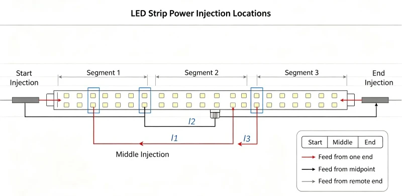
3. Use power injection
Power injection adds electrical connections at additional points along an LED strip or distributed lighting system. Instead of forcing all current through the first section of the strip, power is supplied to multiple sections.
Common approaches include:
Feeding the strip at both ends
Adding injection points at regular intervals
Dividing a long run into separately supplied zones
Connecting parallel branch circuits from a properly sized distribution point
Power injection must be planned carefully. Incorrect polarity, poor connectors, unprotected branch circuits, or overloaded terminals can create safety and reliability problems.
4. Consider a 24 V system instead of 12 V
For the same power, a 24 V system requires approximately half the current of a 12 V system:
120 W at 12 V = 10 A
120 W at 24 V = 5 A
Lower current generally means less voltage drop for the same cable resistance. It may also reduce conductor heating and simplify long-run distribution.
However, 24 V is not automatically better for every project. The LED strip, driver, dimmer, connectors, control equipment, and accessories must all be compatible with the selected voltage.
5. Divide the installation into zones
Large commercial systems should rarely be treated as one continuous circuit. Dividing the project into zones can improve:
Voltage stability
Dimming control
Fault isolation
Maintenance access
Load balancing
Future expansion
Each zone should have correctly sized conductors and suitable overcurrent protection.
Comparison of voltage-drop mitigation techniques
| Solution | Effectiveness | Cost and complexity |
Best suited to |
|---|---|---|---|
| Increase wire gauge | High for cable-related losses | Moderate material cost | Existing systems with long cable runs |
| Shorten the cable run | High | May require layout changes | New construction and accessible installations |
| Add power injection | High for long LED strips | Moderate installation complexity | Continuous strips and linear lighting |
| Change from 12 V to 24 V | Often high | Requires compatible components | New designs and longer runs |
| Divide into zones | High | Higher design and control complexity | Commercial and architectural projects |
For conductor sizing and ampacity requirements, consult the applicable electrical code. For product selection, can review benweilight.com and confirm the driver's output, protection features, control compatibility, and rated load.
Voltage Drop Best Practices in 2026
Managing voltage drop in long LED runs requires attention to both traditional electrical design and newer control technologies. Smart lighting, wireless control, sensors, tunable white systems, and integrated dimming can introduce additional components and operating conditions that must be considered.
When planning a system, review these voltage drop problems in 2026:
Design for the complete system
Do not calculate only the LED load. Include the driver, dimmer, controller, sensors, gateways, emergency components, and any auxiliary devices that share the circuit.
Some systems may draw different current during startup, commissioning, communication, or full-output operation. The design should account for the actual operating scenarios.
Coordinate drivers and controls
A driver may be electrically compatible with an LED fixture but unsuitable for a specific dimming protocol or control topology. Confirm compatibility between:
Driver output voltage
LED load type
Dimming method
Control wiring
Maximum connected load
Minimum dimming load
Cable length and topology
Allow engineering margin
Avoid designing a power supply at its absolute maximum continuous rating. A reasonable design margin can help accommodate temperature variation, manufacturing tolerances, future changes, and real operating conditions.
The appropriate margin depends on the product and application. Follow manufacturer recommendations rather than applying an arbitrary percentage.
Document the installation
Record:
Cable type and size
Circuit lengths
Driver model and output
Load wattage
Injection points
Measured voltage
Control configuration
Commissioning date
FAQ
How do you fix voltage drop in an LED strip?
To fix voltage drop in an LED strip, first verify the load current, cable length, conductor size, and supply voltage. Common solutions include using thicker cable, shortening the power run, injecting power at multiple points, feeding both ends, or changing from a 12 V to a 24 V system where compatible.
Is voltage drop bad for LEDs?
Voltage drop is not automatically harmful, but excessive voltage drop can reduce brightness, cause color inconsistency, create flicker, and prevent a driver or fixture from operating correctly. Persistent electrical stress or overheating may also reduce system reliability.
How much voltage drop is acceptable for LED lighting?
The acceptable amount depends on the LED product, driver, application, and manufacturer requirements. Rather than relying on a universal percentage, calculate the expected drop and compare the measured voltage with the product's operating range.
Is 24 V better than 12 V for long LED runs?
A 24 V system often performs better over long runs because it requires less current for the same power. Lower current generally produces less voltage drop. However, all components-including strips, drivers, dimmers, connectors, and controls-must be rated for 24 V.
Can a larger power supply solve voltage drop?
Not usually. A larger power supply can provide more available capacity, but it does not reduce resistance in an undersized or excessively long cable. Voltage drop must be addressed through cable sizing, run length, system voltage, power injection, or circuit distribution.
Does voltage drop affect LED color?
It can. If reduced voltage changes the current or operating conditions of the LED system, different sections may display different brightness or color characteristics. The effect depends on the LED design, driver type, strip construction, and magnitude of the voltage variation.
Should I use power injection on every LED strip?
Not necessarily. Power injection depends on strip length, power density, voltage, cable design, product specifications, and the required visual uniformity. Follow the manufacturer's maximum-run recommendations and verify the design through calculation and testing.
Conclusion: Build More Reliable LED Lighting Systems
Voltage Drop is a predictable electrical condition, not an unavoidable failure. By understanding Ohm's Law, calculating circuit resistance, selecting appropriate conductors, and distributing power correctly, you can achieve more consistent LED performance across short and long installations.
The most reliable process is to:
Confirm the LED load and operating voltage.
Calculate current and total circuit length.
Select conductors based on voltage drop, ampacity, and local code.
Consider 24 V distribution or multiple power-injection points.
Test voltage at the source and farthest load.
Document the completed installation for future maintenance.
Do not assume that adding a larger driver will solve a wiring problem. A successful design considers the entire system-from power supply and cable resistance to controls, connectors, environmental conditions, and future operating requirements.
For support with product selection, cable planning, or commercial applications, pls contact Benwei for project consultation.
Our Projects